for building frames

The module Joints IV. Bolted – Building frames with rolled and welded steel I sections allows CYPECAD, CYPE 3D and Integrated 3D structures of CYPECAD to carry out the automatic design of the most common bolted connections of rolled and welded steel I sections in building frames. More information on the types of joints that can be designed and the codes available to design them can be found in the Implemented type of building bolted connections section and Implemented codes for the design of building bolted connections section.
- Implemented codes for the design of building bolted connections
- Implemented types of building bolted connections
- Design options
- Prestressed and non-prestressed bolted connections
- Bolted connection design
- Design of building welded connections
- Joint consultation
- Baseplates designed using the Joints IV module
- Joints report
- Bolted joints drawings
- CYPECAD and CYPE 3D modules
Implemented codes for the design of building bolted connections
The following codes have been implemented in CYPECAD, CYPE 3D and Integrated 3D structures of CYPECAD for the design of bolted joints in building frames:
- ABNT NBR 8800 (Brazil)
- ABNT NBR 8800:2008 (Brazil)
- ANSI/AISC 360-05 (LRFD) (USA - International)
- ANSI/AISC 360-10 (LRFD) (USA - International)
- CTE DB SE-A (Spain)
- EAE (Spain)
- Eurocode 3 EN 1993-1-8:2005 (General Document)
- Eurocode 3 NF EN 1993-1-8/NA:2007-07 (With National Application Document for France)
- Eurocode 3 NP EN 1993-1-8:2005/NA:2010 (With National Application Document for Portugal)
- Eurocode 3 UNI EN 1993-1-8:2005 (General Document adapted to Italy)
- IS 800:2007 (India)
- NTC: 14-01-2008 (Italy)
The corrections carried out by the European Committee for Standardization on Eurocode 3 (EN 1993-1-8:2005 / AC:2009) have also been implemented.
The available bolt series, depends on the steel code used for the design. These are indicated in the table below:
Steel codes |
Prestressed |
Ordinary bolt series |
ABNT NBR 8800 (Brazil) |
ASTM A307 |
ASTM A325 |
ANSI/AISC 360-05 (LRFD) (USA - International) |
ASTM A307 |
|
CTE DB SE-A (Spain) |
ISO 7411 |
ISO 4014 |
IS 800:2007 (India) |
ISO 7411 |
Implemented types of building bolted connections
") Beam to column flange bolted moment connection using front plate (at last span of column) |
") Beam to column web and beam to column flange bolted moment connections using front plates (at last span of column) |
") Beam to column web and two beam to column flange bolted moment connections using front plates (at last span of column) |
") Beam to column web bolted moment connection using front plate (continuous column) (Only for CYPE 3D and Integrated 3D structures of CYPECAD) |
") Beam to column web and beam to column flange bolted moment connections using front plates (continuous column) (Only for CYPE 3D and Integrated 3D structures of CYPECAD) |
") Beam to column web and two beam to column flange bolted moment connections using front plates (continuous column) (Only for CYPE 3D and Integrated 3D structures of CYPECAD) |
") Beam to column flange bolted moment connection using front plate (at column transition) |
") Beam to column web and beam to column flange bolted moment connections using front plates (at column transition) |
") Beam to column web and two beam to column flange bolted moment connections using front plates (at column transition) |
") Two beam to column web bolted moment connections using front plates (at last span of column) |
") Two beam to column web and beam to column flange bolted moment connections using front plates (at last span of column) |
") Two beam to column web and two beam to column flange bolted moment connections using front plates (at last span of column) |
") Two beam to column web bolted moment connections using front plates (continuous column) (Only for CYPE 3D and Integrated 3D structures of CYPECAD) |
 Two beam to column web and beam to column flange bolted moment connections using front plates (Only for CYPE 3D and Integrated 3D structures of CYPECAD) |
") Two beam to column web and two beam to column flange bolted moment connections using front plates (continuous column) (Only for CYPE 3D and Integrated 3D structures of CYPECAD) |
") Two beam to column web bolted moment connections using front plates (at column transition) |
") Two beam to column web and beam to column flange bolted moment connections using front plates (at column transition) |
") Two beam to column web and two beam to column flange bolted moment connections using front plates (at column transition) |
") Beam to column flange bolted moment connection using front plate (at last span of column) |
") Beam to column flange bolted moment connection using front plate and simply connected orthogonal beam using lateral plate (at last span of column) |
") Beam to column flange bolted moment connection using front plate and two simply connected orthogonal beams using lateral plates (at last span of column) |
") Beam to column flange bolted moment connection using front plate (continuous column) (Only for CYPE 3D and Integrated 3D structures of CYPECAD) |
") Beam to column flange bolted moment connection using front plate and simply connected orthogonal beam using lateral plate (continuous column) (Only for CYPE 3D and Integrated 3D structures of CYPECAD) |
") Beam to column flange bolted moment connection using front plate and two simply connected orthogonal beams using lateral plates (continuous column) (Only for CYPE 3D and Integrated 3D structures of CYPECAD) |
") Beam to column flange bolted moment connection using front plate (at column transition) |
") Beam to column flange bolted moment connections using front plate and simply connected orthogonal beam using lateral plate (at column transition) |
") Beam to column flange bolted moment connection using front plate and two simply connected orthogonal beams using lateral plates (at column transition) |
") Two beam to column flange bolted moment connections using front plates (at last span of column) |
") Two beam to column flange bolted moment connections using front plates and simply connected orthogonal beam using lateral plate (at last span of column) |
") Two beam to column flange bolted moment connections using front plates and two simply connected orthogonal beams using lateral plates (at last span of column) |
") Two beam to column flange bolted moment connections using front plates (continuous column) (Only for CYPE 3D and Integrated 3D structures of CYPECAD) |
") Two beam to column flange bolted moment connections using front plates and simply connected orthogonal beam using lateral plate (continuous column) (Only for CYPE 3D and Integrated 3D structures of CYPECAD) |
") Two beam to column flange bolted moment connections using front plates and two simply connected orthogonal beams using lateral plates (continuous column) (Only for CYPE 3D and Integrated 3D structures of CYPECAD) |
") Two beam to column flange bolted moment connections using front plates (at column transition) |
") Two beam to column flange bolted moment connections using front plates and simply connected orthogonal beam using lateral plate (at column transition) |
") Two beam to column flange bolted moment connections using front plates and two simply connected orthogonal beams using lateral plates (at column transition) |
 Bolted splice connection of straight equal sections using front plates |
 using front plates") Bolted moment connection of two equal sections (one horizontal and the other inclined, ascending or descending) using front plates |
 Beam to beam bolted simple connection using lateral plate |
 Beam to two beam bolted simple connections using lateral plates |
(1) Joints with continuous columns can only be introduced in CYPE 3D and in Integrated 3D structures of CYPECAD. In CYPECAD, only columns in transition or ends of columns can have this joint.
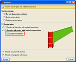
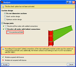
The design options for welded and bolted connections may be configured in the Options menu (Joints > Options). This dialogue box can be accessed via the following menu options:
- In CYPECAD and its Integrated 3D structures:
- Beam Definition tab > Job > Joint analysis options
- Results tab > Joints > Joint analysis options
- In CYPE 3D:
- Joints > Options
This dialogue box contains three tabs:
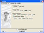
- Non-prestressed bolts
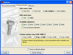
Contains the design options for non-prestressed bolts (Bolt series code, Bolt steel class and Available diameters). Options selected here will only affect bolted connection design. - Prestressed bolts
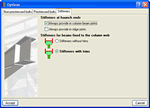
Contains the design options for prestressed bolts (Bolt series code, Bolt steel class, Available diameters and Friction surface class). Additionally, the type of friction surface must be indicated to check the bolt for slipping. Within this dialogue, the program also defines the properties of the selected surface in accordance with the article of the selected code. Options selected here will only affect bolted connection design. - Stiffeners
Contains two option groups which configure the layout of the stiffeners:- Stiffeners at haunch ends
Contains two options which when activated force the program to always provide stiffeners, one in column to beam connections and the other in ridge connections. Affects welded connections designed with the Joints I module and bolted connections designed with the Joints II module.
Regardless of whether this option is activated or not, the program always provides stiffeners at the ends of the haunches if the design requires their presence. - Stiffeners for beams fixed to the column web
Activates the trimming of stiffeners for beams fixed to column webs. It only affects welded connections designed with the Joints III module and bolted connections using the Joints IV module (the other modules do not contemplate connections consisting of beams fixed to column webs).
This option does not imply changes in the structural check but only takes into account aspects related to the aesthetics and with the number of trimming operations undertaken in the fabrication process. Upon activating the trimming option, it will be carried out if the following conditions are met:- The smallest side of the trim has to be greater than 10mm.
- The angle formed between the inclined side of the trim and the plane perpendicular to the web has to be greater than 15 degrees.
- Stiffeners at haunch ends
Prestressed and non-prestressed bolted connections
CYPECAD, CYPE 3D and Integrated 3D structures of CYPECAD allow bolted connections to be designed using prestressed or non-prestressed bolts. This option is located in the Analysis menu (Analysis > Analyse) or in the joints design dialogue box (Joints > Analyse).
When the structure is analysed taking into account seismic effects, the program either recommends or imposes the use of prestressed bolts depending on the selected seismic code. If the code states the use of prestressed bolts is obligatory, the program selects this option and does not allow for it to be deactivated. If the seismic code does not state it is compulsory to use prestressed bolts, the program reminds the user it is advisable to use these as is recommended by Eurocode 8.
When bolted connections are used, the program also indicates the friction surface class to be used in case that selected by the user in the design options is not adequate.
If the warnings are not taken into account by the user, it is possible for the prestressed bolted connection to not be designed by the program. In this case, when the user consults the joints after the analysis, the program indicates as errors the reasons why the design has not been carried out.
If during the analysis process of the structure, nodes are detected whose configuration is adjusted to those types resolved by the program, they will be designed and detail drawings, 3D views, code check reports and take-off of these designs will be provided.
The program designs the dimensions of the plates and stiffeners, the optimum number and layout of the bolts and the throat thicknesses of the welds required for the correct stress transmission in the connection.
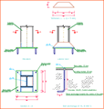
The program designs the bolted connections using a front plate or a lateral plate:
- Moment connections using front plate. This type of solution is used by the program for fixed connections between beams and columns, for element splices and ridge beam connections.
- Simple connections using lateral plates. This type of solution is used by the program for pinned connections between beams and column webs or flanges, and webs of other beams (secondary beams).
- Simple connections using front plates. This type of solution is used by the program for beams supported at column ends forming a pinned connection.
When welded or bolted connections are designed, or when the structure is analysed together with the joints, the program carries out, at each node of the job, the spatial layout of the bars and its fixity conditions in such a way that, for steel bars, the dimensions of the nodes are established and generates the rigid ends in which the portions of the bars are considered to not deform due to them being contained within the node.
Rotational stiffnesses at element ends
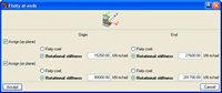
The program allows for fixity coefficients xy and xz or rotational stiffnesses to be assigned to bar ends (bars or set of aligned bars forming one element). Defining the rotational stiffness allows for the joints to be modelled and whereby their stiffness to rotate is fundamental to bear into account, as is in the case of bolted connections.
For each bolted connection that is designed, the program analyses (for all the acting force combinations) the rotational stiffness of the end of each fixed element and suggests a value with which the structure is to be reanalysed. The proposed stiffness will be the smallest amongst those calculated at each element end, which corresponds to the one with the greatest positive or negative moment.
After the analysis and for elements fixed to the bolted connections, if the user has not defined the rotational stiffness or if the introduced value differs in more than 20% from that proposed by the program, a warning is emitted. This is also displayed as a warning in the report at the end of the analysis or in the option Show error messages in the Analysis menu.
Using the Rotational stiffnesses option in the Joints menu, the user can manage and substitute the values that were introduced instead of those proposed by the program (at the ends of elements with moment bolted connections provided by the program). This option activates a dialogue box with two possibilities:
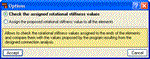
- Check the assigned rotational stiffness values
Displays the element ends whose rotational stiffnesses are adjusted to those proposed by the program in green; whilst those with a stiffness differing in more than 20% to that proposed by the program are shown in red.
By placing the cursor over one of these element ends, the program displays a tag with the messages associated to that end and highlights in blue all the element ends of the structure that follow the same behaviour, moment-rotation diagram and assigned rotational stiffness.
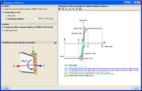
By selecting the end of the desired element, a dialogue box is displayed containing information on the type of fixity assigned to the end of the element and the rotational stiffness value proposed by the program, as well as the behaviour graph of the connection expressed by a moment-rotation curve.
In this dialogue box, the original values can be maintained or modified. If they are modified, all the elements of the same type will be affected (those highlighted in blue when an end was selected). This dialogue box also contains a help button ( icon)
in which the criteria followed by the program to obtain the rotational stiffness proposed
by the user is thoroughly explained.
icon)
in which the criteria followed by the program to obtain the rotational stiffness proposed
by the user is thoroughly explained. - Assign the proposed rotational stiffness value to all the elements
Automatically assigns the rotational stiffness values proposed by the program to all the following element ends (only at element ends fixed with bolted connections).
- Those whose introduced rotational stiffness differs in more than 20% to that proposed.
- Those for which the user has not indicated any rotational stiffness.
![]() After assigning the rotational stiffnesses proposed by the program to the desired element
ends, the structure must be reanalysed so the new force distribution due
to the change in the rotational stiffnesses can be taken into account. The program emits
a warning of this situation.
After assigning the rotational stiffnesses proposed by the program to the desired element
ends, the structure must be reanalysed so the new force distribution due
to the change in the rotational stiffnesses can be taken into account. The program emits
a warning of this situation.
Design criteria for prestressed bolted connections
The shear check in the transverse section of the bolts is substituted for an Ultimate Limit State (U.L.S.) slip check in the case of prestressed bolted connections and the tension and slip interaction is analysed.
When the user activates seismic action for the analysis of the structure, the fixed prestressed bolted connections are designed for Failure Mode 1, i.e., failure will occur due to plastic failure of the front plate of the connection and not due to bolt failure. Therefore, when the seismic action is taken into account, bolts are designed using greater diameters to guarantee enough rotation capacity.
Design of building welded connections
Joints IV in CYPECAD, Integrated 3D structures and CYPE 3D
As occurs with the Joints I and Joints II modules and Joints III module, the Joints IV. Bolted – Building frames with rolled and welded steel I sections module designs the joints at floor level (with column transition) and at column ends. In the case of CYPE 3D and Integrated structures of CYPECAD, as the concept of floor level does not exist, the joints may be placed at an intermediate level of a column span (continuous column) and at the connecting node between two different column spans (a transition plate between the two column spans is provided).
Depths of beams with simple or moment connections to columns
Elements with simple or moment connections to columns can have differing depths.
Beam to column moment or simple connections
- Sloped beams at joints with elements fixed to the column web and flanges
In this case, the beams may be inclined with respect to the horizontal plane if the elevations of the top or bottom beam flanges coincide at the cut-off point of the joint.
- Sloped beams at joints with elements fixed to the column flanges and pinned
to the column web
In this case, elements fixed to the columns may be inclined with respect to the horizontal plane if the joint occurs at the end of a column. At floor level or at intermediate column spans, these beams must be horizontal. To be able to design these joints with sloped beams at any column span, the user license must have the necessary permits to be able to use the Joints II module.
Beam to column moment connections
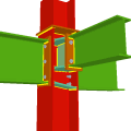
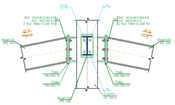
Using the Joints IV module, joints consisting of beams fixed to the column web and flanges can be designed.
- Beams fixed to column flanges
- Stiffeners
Stiffeners are always provided in correspondence with all the flanges.
When the elevation difference between the beam flanges which are to be fixed to the column flanges is small, a stiffener cannot be welded correctly to each flange. In these cases, the Joints IV module may design the joints using two construction solutions:
- A single horizontal stiffener between both flanges. This is used when the free distance between the column flanges is less than or equal to the thickness of the stiffener.
- A inclined stiffener between the flanges. This is used when the free distance between
the beam flanges is greater than the thickness of the stiffener and less than the
distance which allows for two stiffeners (one for each flange) to be placed.
In these cases the user must bear in mind that the program does not allow for a beam that is fixed to the web to bear on an inclined stiffener.
- Coplanar webs
The webs of the beams must be in the same plane as the column web - Haunches
The Joints IV module does not use haunches in its joint design, as they are not usually used in building frames. To be able to place haunches at elements fixed to column flanges, using CYPE 3D or the Integrated 3D structures of CYPECAD, the user license must have the necessary use permits for the Joints I (welded) and Joints II (bolted) modules.
- Stiffeners
- Beams fixed to column webs
Beams fixed to column webs bear on front plates, which are connected to the web of the column by means of the following welded elements:
- Plate perpendicular to the column web which allows the beam to behave as a continuous element between the front plate and the web of the column.
- Stiffeners in correspondence with the flanges of the beam fixed to the column web or with the stiffeners placed by the beams fixed to the column flanges.
Beam to column simple connections
The Joints IV module designs joints containing one or two elements pinned to the web of a column if there is at least another beam fixed to the one of the column flanges.
Moment connection between beams with coplanar webs
Using the Joints IV module, the fixed connection between two elements with coplanar webs can be designed, as long as the following conditions are met:
- Two continuous elements (splice connections) in any direction and with the same depth.
- One of the elements must be horizontal and the other inclined (ascending or descending). The depths of the beams must be the same.
- No haunches are provided.
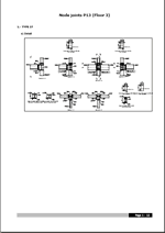
Following the analysis, the joints that have been designed by the program can be consulted.
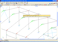
CYPE 3D and CYPECAD place different coloured circles at the nodes to indicate whether or not all the connections of the node have been designed, if there are only a few that have been designed or if the node does not contain any designed connections.
If the cursor is brought close to a node in which there are connections that have been designed, an information window will appear indicating the types of connections designed for that node. By clicking on the node a dialogue box with three tabs is displayed containing the following information:
- The construction details of the resolved connections
- A report of the checks and take-off of the resolved connections
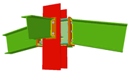
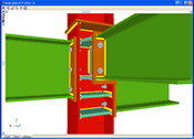
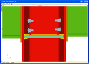
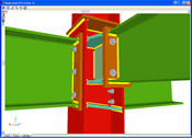
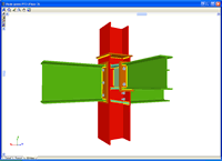
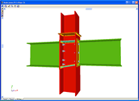
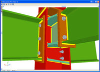
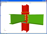
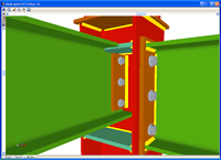
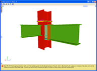
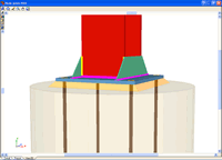
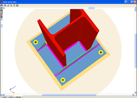
- Real 3D views of the connections. It is possible to visualise a 3D view of each connection designed by the program with an isometric or conical perspective. The elements making up the joint (columns, beams, stiffeners, welds, bolts and plates) are drawn in different colours. Prestressed bolts and non-prestressed bolts are also represented in two colours to differentiate between them. The user may also freely rotate and amplify the 3D view. These characteristics greatly help the user to understand the assembly of the joint. The 3D view of the joints can be visualised by selecting the 3D view tab that appears in the bottom part of the window that is activated upon consulting the joint.


If the cursor is brought close to a node in which there are no designed connections, but belongs to one of the connections recognised by the program, a window appears informing of the causes that have prevented that joint from being designed.
Even if the user license has not acquired the joints modules, the program allows the user to activate the joint design process. Once the process has concluded, the user can see the 3D views of the joints that could be resolved with the non-acquired modules, even though neither the joint details, check reports nor take-off reports are displayed. When the cursor is placed over one of these nodes, a warning appears indicating the non-acquired modules used to design the joint.
Baseplates designed using the Joints IV module
The Joints IV. Bolted – Building frames with rolled and welded steel I sections designs baseplates on footings, piles and mat foundations.
The Joints IV module also designs the baseplate connection points of integrated 3D structures, if these are located on footings, pile caps, slabs, shear walls, walls, concrete columns or beams (in the case of these last four elements, they are designed if no other steel beams or steel bars of the integrated 3D structures connect at that node).
The designed baseplate properties include:
- Type of baseplate: rolled and welded steel I section baseplates are designed
- Welds: Includes the analysis and design of plate, stiffener, column and bolt welds.
- Automatic match: Automatically matches the baseplates of the same job (bearing in mind the type of section, the forces and external fixities). This way and without the user having to intervene, the number of different types of plates is reduced, obtaining more uniform results.
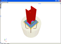
- 3D view with colour representation of the elements and welds: A 3D view can be seen on screen whereby the plate, column, stiffeners, bolts, welds carried out on site and in the workshop are displayed in different colours, in the same way as with I section connections. This helps to obtain a better understanding on how the support is assembled.
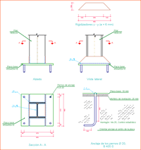
- Baseplate details: Baseplate details are generated in which the design weld details are displayed as well as those corresponding to the stiffeners. These details can be included in the job drawings.
- Code check and takeoff reports: Code check and takeoff reports of the baseplates are generated, integrated with the rest of the designed connections.
More information on baseplate design can be found in the Baseplate section of CYPE 3D.
- Baseplates designed using the Joints I, Joints II, Joints III and Joints IV modules
- Baseplates designed using the baseplates module
- Design options for baseplates
- Baseplate checks
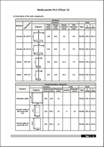
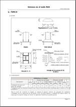
CYPE 3D and CYPECAD generate a joints report with the following data:
- Welded connection specifications
- Code
- Materials
- Construction layout
- Checks
- Bolted connection specifications
- Code
- Materials
- Construction layout (includes conditions and possible fastening methods of prestressed bolts)
- Checks
- References and symbols
- Baseplate checks
- Relationship of the designed joints
- Calculations
- Construction detail of each type of joint
- Description of the components of each type of joint
- Check results of each type of connection
- Weld, plate and bolt take-off for each connection type
- Complete take-off of welds, plates and bolts of the designed joints
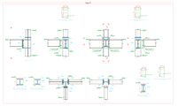
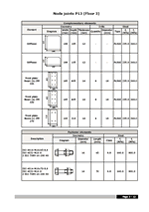
The construction details of the joints designed by the program can form part of the drawings of the structure. The Joints drawings include the following elements:
- Construction detail of the joint
- Schedule with specifications of the welds in steel structures
- Code
- Materials
- Construction layout
- Fastening procedure of prestressed bolts
- Checks
- Reference and symbols table
- Complete take-off of welds, plates and bolts of the designed joints
CYPE 3D modules:
CYPECAD modules:
- Steel columns
- Steel beams
- Joist floor slabs (generic concrete joists)
- Joist floor slabs (in-situ, precast and steel)
- Timber joist floor slabs
- Waffle slabs
- Flat slabs
- Punching shear verification (Also operates as an independent program)
- Composite slabs
- Hollow core slabs
- Post-tensioned concrete slabs for buildings
- Shear walls
- Reinforced concrete walls
- Plane stress walls
- Stairs
- Mat foundations and foundation beams
- Concrete block walls
- Interaction of the structure with the construction elements
- Automatic job introduction: DXF, DWG and CAD/BIM models
- Collective protection systems
Modules common to CYPECAD and CYPE 3D:
- Concrete columns
- Composite steel and concrete columns
- Concrete beams
- Timber sections
- Pile caps (includes strap and tie beams)
- Baseplates
- Footings (pad and strip) (includes strap and tie beams)
- Advanced design of surface foundations
- Fire resistance check
- Parallel analysis with two multiprocessors
- Parallel analysis with up to eight processors
- Joints I. Welded. Warehouses with rolled and welded steel I sections
- Joints II. Bolted. Warehouses with rolled and welded steel I sections
- Joints III. Welded. Building frames with rolled and welded steel I sections
- Joints IV. Bolted. Building frames with rolled and welded steel I sections
- Joints V. Flat trusses with hollow structural sections
- Export to Tekla
Tel. USA (+1) 202 569 8902 // UK (+44) 20 3608 1448 // Spain (+34) 965 922 550 - Fax (+34) 965 124 950